Understanding Relays & Wiring Diagrams
- What is a Relay and How Does it Work?
- Why Use a Relay?
- Why Use a Relay in a Car?
- How to Understand the Electrical Specifications of a Relay
- Why are Protection Devices used in a Relay?
- What’s the difference between 4 and 5 pin Relays?
- 4 & 5 Pin Relay Schematics
- What are ISO Relays Used For?
- Types of Relays
- Relay Schematics and Diagrams
What is a Relay and How Does it Work?
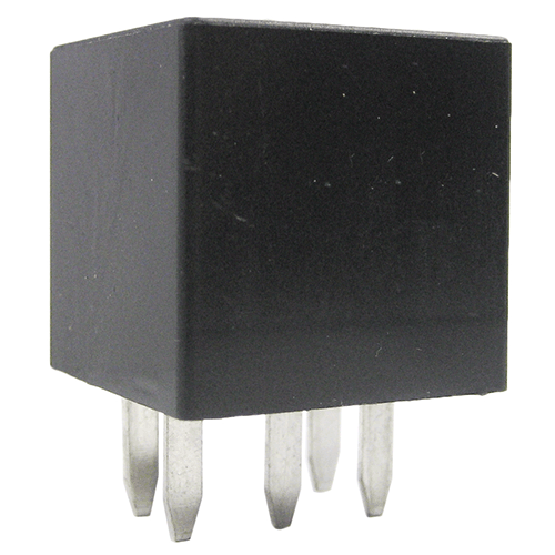
A relay is an electrically operated switch. They commonly use an electromagnet (coil) to operate their internal mechanical switching mechanism (contacts). When a relay contact is open, this will switch power ON for a circuit when the coil is activated.
The example relay diagrams below show how a relay works.
We stock a large range of relays & relay holders all available for purchase directly from our website.
The example relay diagrams below show how a relay works.
We stock a large range of relays & relay holders all available for purchase directly from our website.
Why use a Relay?
Relays allow a low current circuit to control one or more higher current circuits. Relays provide these benefits;
1. Thinner cables can be used to connect the control switch to the relay thereby saving weight, space and cost.
2. Relays allow power to be routed to a device over the shortest distance, thereby reducing voltage loss.
3. Heavy gauge cable only needs to be used to connect a power source (via the relay) to the device.
Why Use a Relay in a Car?
There are several benefits of using a relay in a car. Firstly using a relay means the switching circuit does not require a high current rated switch or cable which reduces cost and weight. Secondly, relays can be positioned anywhere in the vehicle to provide efficient power transfer to the electrical accessory you are controlling. Relays are perfect for controlling many circuits in a car like headlights, electric motors, heater etc.
How to Understand the Electrical Specifications of a Relay
Basic relays feature electrical ratings for both the coil and the internal switching contacts. The coil voltage rating is
the voltage required for the coil to operate correctly. The switching circuit of the relay also features a voltage and
ampere rating. This is the maximum rating of the switch contacts and should NOT be exceeded. Double throw
relays often have 2 x switch electrical specifications. One for the normally open terminal, the other for the normally
closed terminal. ie. N/O: 35A at 14vdc, N/C: 20A at 14Vdc.
Why are Protection Devices used in a Relay?
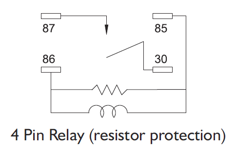
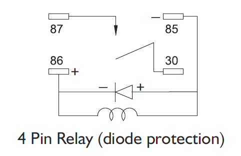
Relays can produce a large voltage spike when they are switched off due to the coil de-energising. Resistors or
diodes are sometimes fitted across the coil of the relay to stop/reduce these spikes travelling back into the control
circuit and damaging sensitive components. Resistors are more durable than diodes, but not quite as efficient at
eliminating voltage spikes. You need to assess the sensitivity of the components in the control circuit when
deciding if / what type of protection is required.
Sample Wiring Diagrams for a 4 Pin Normally Open Relay
What’s the difference between 4 or 5 pin Relays?
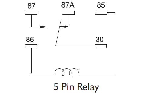
The difference between a 4 and 5 pin relay is that a 4 pin relay is used to control a single
circuit, whereas a 5 pin relay switches power between two circuits.
4 Pin Relay
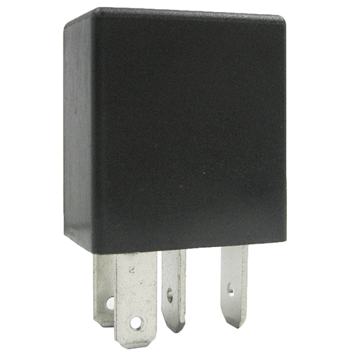
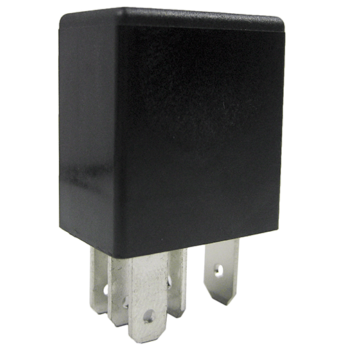
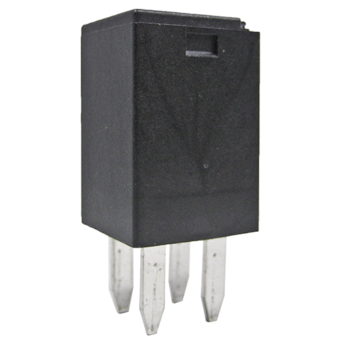
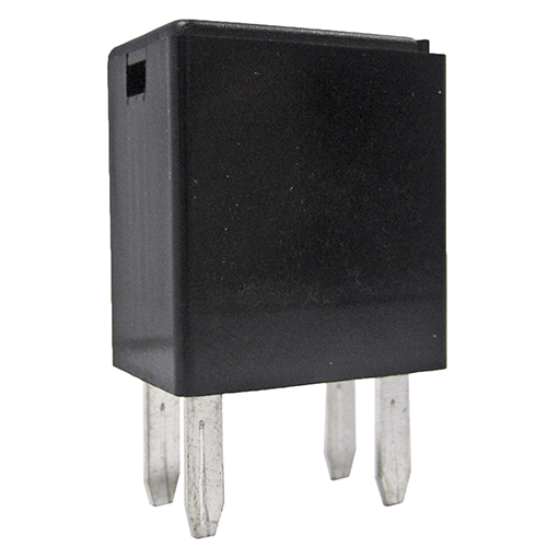
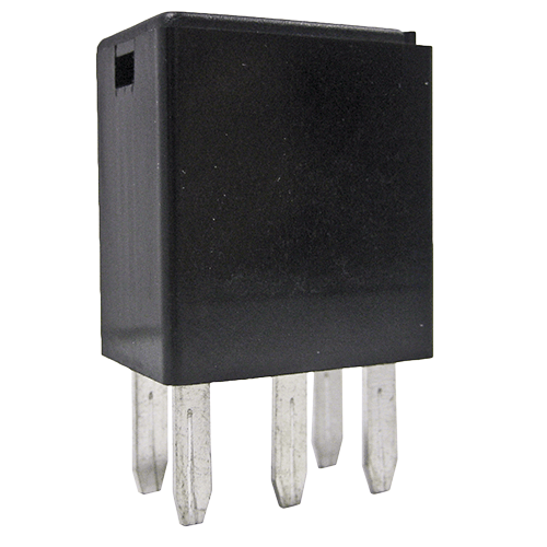
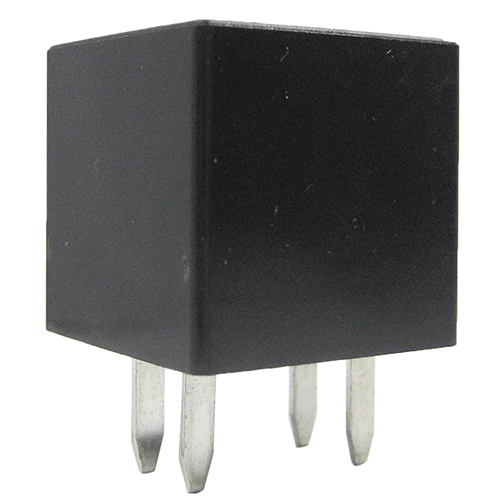
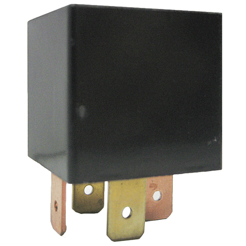
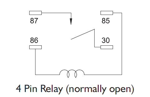
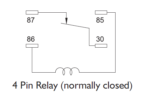
4 pin relays use 2 pins (85 & 86) to control the coil and 2 pins (30 & 87) which switch power on a single circuit. There are 2 types of 4 pin relay available; normally open or normally closed. A normally open relay will switch power ON for a circuit when the coil is activated. A normally closed relay will switch power OFF for a circuit when the coil is activated.
5 Pin Relay
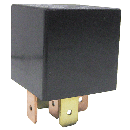
5 pin relays provide 2 pins (85 & 86) to control the coil and 3 pins (30, 87 & 87A) which switch power between two circuits. They have both normally open and normally closed connection pins. When the coil is activated, power will be switched from the normally closed pin to the normally open pin.
What are ISO Relays Used For?
ISO relays are designed for use in the automotive industry and adhere to a standard pattern for their electrical
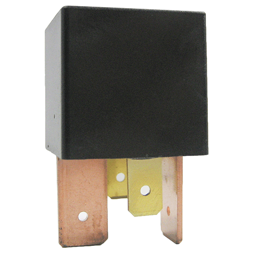
terminals. The newer ISO 280 relays use a smaller pin terminal that is 2.8mm wide and can be used in compact
power distribution units and holders.
Standard ISO Relays
We sell both 4 pin normally open (SPST) and 5 pin change-over (SPDT) relays with resistor
protection in either 12V or 24V ratings. Should you require diode protection, please contact sales.
New ISO 280 Relays
We sell both 4 pin normally open (SPST) and 5 pin change-over (SPDT) relays with resistor
protection in either 12V or 24V ratings. Should you require diode protection, please contact sales.
Sample Wiring Diagrams for a Normally Open Relay
Example 1. 4 pin (normally open) relay with the switch on the positive side of the control circuit.

Example 2. 4 pin (normally open) relay with the switch on the negative side of the control circuit.
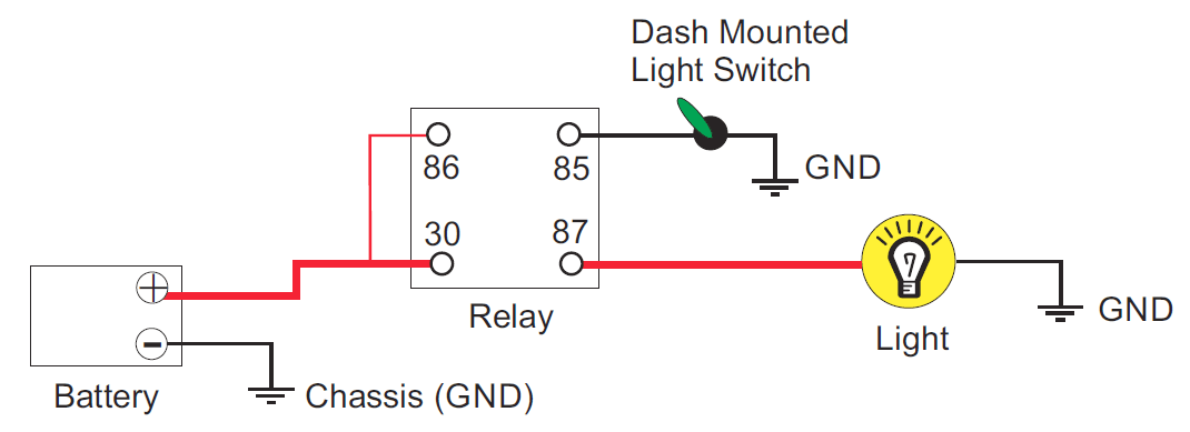
Note: These circuits have been simplified to illustrate the function of a relay and therefore exclude fuse
protection that would be required. Relay coil terminals have no polarity unless the relay coil is protected by a
diode (inside the relay) in which case the coil terminal wired to the diode’s anode must be connected to negative.
Relay Holders
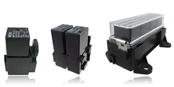
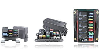
We sell a wide range of holders for ISO and ISO 280 relays that can fit one or multiple
relays. We also have a large range of power distribution units that can be fitted with a
mixture of relays, fuses & circuit breakers.


